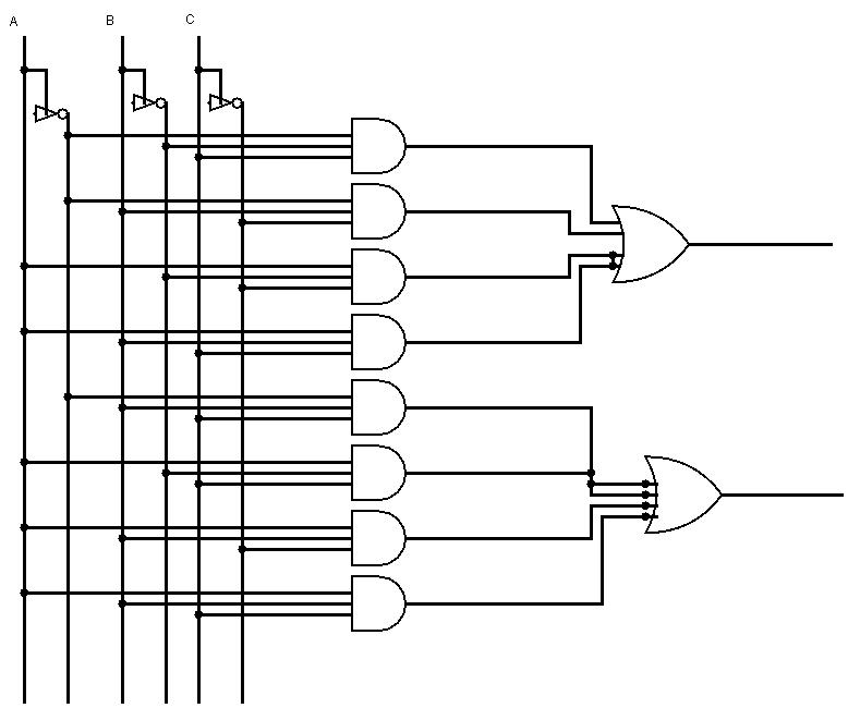
Block Diagram Of Full Adder Circuit
Full adder circuit: theory, truth table & construction Adder logic gates theory binary circuits numbers bits calculator equations gupta Adder half xor rangkaian logic ripple adders transistor kombinasi
Full Adder Circuit Diagram
Computer adder block diagram Full adder : circuit diagram, truth table, equations & verilog code Full adder
Adder full diagram bit subtractor circuit block using logic 6m jun2006 carry map draw create
Half adder circuit diagramDraw the circuit diagram of half adder Circuit diagram of 4 bit full adderHow many bits can a full adder add?.
Adder full table truth diagram block digital electronics javatpoint4-bit parallel adder circuit diagram Half adder circuit: theory, truth table & constructionHalf adder circuit block diagram.

Full adder circuit diagram
Draw the logic diagram of a full adder. create a 2-bit adder-subtractor13+ full adder block diagram Adder full circuit diagram using truth table carry 4bit construction schematic shown chip ttl ahead feature below lookAdder combinational logic circuits.
Block diagram of full adder circuitAdder full circuit truth table diagram block construction carry 8-bit adder circuit diagramAdder full diagram circuit cin theorycircuit.

Full adder circuit – how it works
Full adder circuit diagramAdder in digital electronics, half adder and full adder in digital Fast adder circuit diagramAdder circuit logic truth schematic circuitglobe circuits robhosking xor representation compressor sum.
Adder circuit diagram schematic bit full works figureAdder binary vidi theory gupta sourav Adder full half block diagram electronics digital two three inputs sum carry outputs receives produces circuit shown belowAdder in digital electronics, half adder and full adder in digital.

Adder circuit full logic using digital boolean implementation diagram implement function
Full adder circuit: theory, truth table & constructionFull-adder circuit, the schematic diagram and how it works – deeptronic Full adder em digital logic – acervo limaExplain full adder with truth table and logic circuit diagram.
13+ full adder block diagramAdder full diagram block circuit gates using basic truth table Combinational logic circuits : definition, examples, and applicationsAdder input outputs along.

Full adder circuit diagram
How to build a full adder8 bit full adder circuit diagram Circuit diagram full adder subtractor8 bit binary adder circuit diagram.
Explain full adder with circuit diagramDigital logic design: full adder circuit Full adder circuit: theory, truth table & constructionAdder lookahead vhdl verilog.


