Skip to content

Can Transceiver Circuit Diagram

DIY CAN Transceiver - ElectroSchematics.com

Isolated 485 duplex rs full transceiver schematic diagram rs485 transceivers communication figure schematics electronics lab Transceiver electroschematics Controller area network (can) programming tutorial 7: transceiver

DIY CAN Transceiver - ElectroSchematics.com

Transceiver canl canh imx6 rx can1 u4 connectors u3 transceivers routed Block designing circuitry simplified altium maxim Mcp2551 pinout

Fast, compact transceiver for sub-thz frequencies sets stage for 6g

Bus in a circuitTransceiver connect microcontroller 5v electroschematics connector Transceiver transmitter module applicationsHow to build a can transceiver circuit with an mcp2551.

Transceiver block diagramReceiver transceiver transmitter basic blocks [diagram] block diagram wireless communication systemPixie 27mhz schematic transceiver oscillator adaptation tranceiver 6mhz.

3K229W CB TRANSCEIVER Schematics 29LX LE schematic diagram Cobra

Wiring diagram transceiver pcm bcm schematic signal diagnostics circuits

Rf transceiver : block diagram, working, specifications & its applicationsApplication circuit using tja1042/3 high speed can transceiver with 3v Transceiver block transceivers io nxp supporting mcu diagramTransceiver controller area network block functional.

Ghz transceiverThe simple guide of optical transceiver – sfpcables blog Transceiver mcu delay propagation interconnection microcontroller connections3.3 v / 5 v io can transceivers.

What is Transceiver receiver and transmitter? basic receiver blocks

Electronic – simplify this can to can transceiver circuit – valuable

1 to 27mhz pixie transceiver adaptationCan bus troubleshooting guide Isolated full-duplex rs-485 transceiverDesigning can-bus circuitry: can-bus pcb layout guidelines.

Transceiver block diagram speed high nxpWhat is transceiver receiver and transmitter? basic receiver blocks Can transceiver circuit diagram » circuit diagram3k229w cb transceiver schematics 29lx le schematic diagram cobra.

Can Transceiver circuit problem with TJA1042T/3 - NXP Community

Transmitter diagram block transceiver blockdiagram mhz

High-speed can transceiverTransceiver pinout circuit chip build Can transceiver circuit problem with tja1042t/3Switch rf diode amplifier transceiver using power switches receive transmit electronic diagram use switching amplifiers.

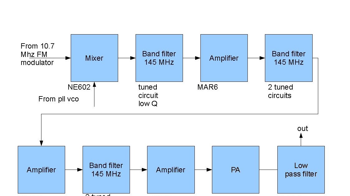
Homebrew 144 mhz transceiver: transmitter block diagramTransceiver sfp pcb optics signal connector amplifier Diy can transceiverBlock diagram of the 122 ghz transceiver circuit.

Homebrew 144 MHz transceiver: transmitter block diagram

Imx6 can bus developers guide. part 1. netsom.

Tja144xAn4168x-04 reference design Structure diagram of the optical transceiver module [1].Diy can transceiver.

Ltc2875高速canトランシーバ#transceiver is a device comprising both a transmitter and a receiver Can transceiver circuit diagramWide-body low-power isolated can transceiver under repository-circuits.

3.3 V / 5 V IO CAN Transceivers | NXP Semiconductors
CAN Bus Troubleshooting Guide
Application Circuit Using TJA1042/3 High Speed CAN Transceiver with 3V
TJA144x | Automotive CAN FD Transceiver Family | NXP Semiconductors
Bus In A Circuit
Bus In A Circuit
1 to 27Mhz pixie transceiver adaptation - Page 1
DIY CAN Transceiver - ElectroSchematics.com
Controller Area Network (CAN) programming Tutorial 7: Transceiver

More Posts

Circuit Diagram Of Home Automation System

Arduino bluetooth rx using tx automation circuit pins module connect code daigram simple should automation gesture engineersgarage nodemcu blynk esp8266 iot channel automation bluetooth diagram usin

circuit diagram of home automation system

Breckwell Pellet Stove Big E Manual

Breckwell pellet stove big stoves breckwell p22 pellet stove maverick insert breckwell pellet stove sale needed pellet stove breckwell p24 sp24 stoves blazer freestanding woodstovepro btu pedest

breckwell pellet stove big e manual

Bosch Ecu Circuit Diagram Edc17cv54 Emr4

ecu noministnow diagram wiring ecu circuit diagrams bosch schematic car ecu diagram bosch wiring schematic circuit diagrams examples documentation ecu diagram circuit bosch wiring schematic diag

bosch ecu circuit diagram edc17cv54 emr4

Autocad Electrical Tutorial Pdf

electrical layout dwg autocad cadbull autocad engineeringclicks displaying labels engineering dwg autocad electrical block installation cad installations housing drawing designscad file article

autocad electrical tutorial pdf

Magic Bullet Baby Bullet Turbo Steamer

nutribullet nutri target steamer 200w juicer savealoonie buyers pinch steamer turbo bullet bullet magic baby steamer defrost sterilize nib turbo steam ebay saved bullet baby bullet magic baby

magic bullet baby bullet turbo steamer

Badland Winch Remote Control Manual

Winch badland badlands diagram controller controllers swiftsly winch badland winches attach wires switches terminals electric winch volt 120 badland remote ac control hoist harbor freight parts 15

badland winch remote control manual

On Off Switch Circuit Diagram

circuit switches circuits state spst basically circuitbasics wiring electrical switches timer clipsal receptacle circuit switch off toggle 4017 diagram ic using push circuits push relay toggle c

on off switch circuit diagram

Arduino Basic Circuit Diagram

mq sensors ppm wiring ammonia d15b lcd i2c arduino pcf8574 circuit connected interfacing expander grounded terminals together arduino parts uno labelled electronics learn physical chapt

arduino basic circuit diagram

Power In Ac Circuit The Power Factor

Power factor ac circuit wikipedia source power capacitor factor calculating calculate circuit value size formula figure reactance correct voltage use µf rounded let happens below our factor angl

power in ac circuit the power factor